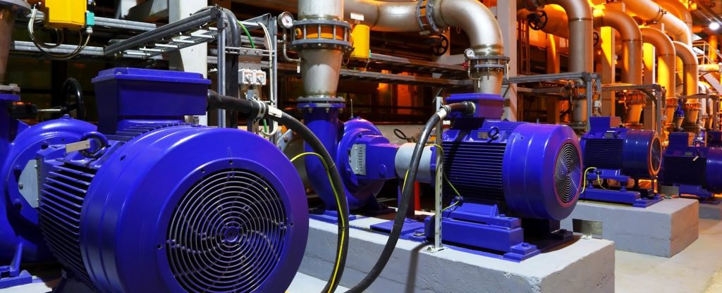
DRIVE SYSTEM
Proper Sizing is a crucial facet of motor selection. When a motor is undersized, it won’t be able to restrain the load, resulting in overshoot and ringing. It is very necessary for Sizing a Motor.
Over-sizing a system is as bad as under-sizing — it may control the load but it will also be bigger and thicker; as well as more expensive concerning price and cost of operations. It may not physically fit and it surely will cost more. It will use up more valuable space at a control cabinet or around the store floor.
What to think about when purchasing a motor?
All too frequently, vendors simply get a call asking for an engine of a particular horsepower. The engineer may be buying a motor exactly the same size as that of a former platform. They might have added a hefty security allowance to compensate for modifications. They might have utilized a 10:1 or 5:1 ratio of load and inertia to motor inertia — or any mix of the above mentioned.
The Goal must be to define a motor that offers the speed; acceleration; and torque necessary to position the load at the specified place and the desired time. The safety margin ought to be added on top of an educated calculation, nevertheless. Not only that you also need Industrial Automation Courses in Kolkata.
A common mistake is to choose a motor with a continuous-duty torque equivalent to the highest torque requirement of the application (typically seen through intense accelerations/decelerations). Motion control software often consists of short, rapid moves. To choose a motor rated to make this torque continuously means basically paying for more engine than necessary.
Sizing a Motor
To effectively size the motor, it’s essential to calculate the load inertia (JL).
The proportion of load inertia to motor inertia (basically, rotor inertia) provides a measure of how efficiently the motor can control the load. A high inertia ratio suggests the system that will have difficulty controlling the load. Often, Designers incorporate the real load, the gearbox, and the engine, but leave belts, pulleys, and other mechanical things out of this equation. They simply move to the next major size or use the same frame size but one that generates more torque. This is where the whole 10% oversize approach comes from. Be sure that you are efficient in Sizing a Motor.
The Selection process involves the collection of information followed by a detailed investigation. It demands knowledge of the mechanical system, the operating parameters, as well as the conditions under which the equipment is going to be used. It must also include details of the operating environment, for if these are not considered at an early stage, the chosen system may not be appropriate.
Inertia —
the tendency of an object to resist changes in acceleration — is one of the chief challenges in movement control. The motor has to be able to apply sufficient force (in a linear system) or torque
(in a rotational system) to change the acceleration of the load and do this in a controlled fashion.
The Main constraints that have to be thought about during the sizing procedure could be summarized as follows:
1. Peak Torque
2. RMS Torque
3. Maximum rate
4. Motor speed-torque features
In Addition, two application regimes need to be considered:
• Continuous duty program
• Intermittent duty program
The difference between these two program regimes can be exemplified by means of a lathe. The spindle push of a lathe is a continuous duty application, as it runs at a constant speed under continuous load; the axis drives would be an irregular obligation application, as a result of acceleration and deceleration necessary to follow the mandatory tool path.
Speed and Motors
The Drives of robots and machine tools always change speed to create the essential motion profile. The choice of the gear ratio and its relationship to the generated torque of the engine needs to be fully considered. If the load must operate at a constant speed, or torque, then the best gear ratio can be determined. In practice, instances to be considered include acceleration with without an externally applied load skate as well as the effects of variable load inertias.
Knowledge of the essential speed assortment of the load along with also an original estimation of the equipment ratios required will permit the summit motor speed to be anticipated. To protect against the motor not attaining its required speed, due to fluctuations in the supply voltage, the highest rate demanded ought to be raised by a factor of 1.2. This variable is satisfactory for most industrial software , but might be refined for a unique application, such as once the system must operate from a restricted supply as found in applications as varied as aircraft and offshore petroleum platforms.
Voltage
Since the Peak speed of a motor is dependent on the supply voltage; intervals of reduced voltage need to be thought about. As a principle, a driveway is normally sized so it could run at peak rate at 80% of the nominal voltage. When a system is fed from a source vulnerable to brownouts or blackouts; considerable care will have to be taken to ensure that the drive; its own controller and the load are safeguarded from damage; this is particularly severe with microprocessor systems, which, if not correctly configured, can lock-up or reset without warning, causing a possible catastrophic situation.
Where A motor-drive mix is going to be required using a peak torque capacity of at least 1.5 to two times that value to ensure sufficient torque capability.
The Peak torque of the motor-drive combination must exceed, by a safe margin of at least 15%, the amount of the estimated friction torque plus acceleration torque plus any constant torque loading gift during acceleration. If this is not achievable, a different motor or gear ratio will probably be required.
On very High-performance machines, the most recent crop of auto-tuning drives can very efficiently compensate for machine resonances and vibration, encouraging precise performance even at very high speeds. Electromagnetic compatibility has a considerable influence on the design and application of a system.
Power Transmission Components
The Mechanical needs of the motor must be recognized at an early stage from the sizing and selection procedure. Frequently overlooked items include any dimensional and orientation limitations resulting from the mechanical design in Sizing a Motor.
If these can be identified at an early stage it may prevent disappointing performance when the gear is installed. Specifically, if the engine is mounted in the vertical position, specific shimming or bearing preloads may be deemed necessary.
In the Determination of the driveway requirements, friction torques are possibly the toughest aspect of the engine pruning procedure.
Bearings
In the event of a rotating shaft, a bearing is the most frequently used method of support.
Many different kinds can be found, of which the most typical is that the roller and ball bearing.
Gearboxes
A Standard gear train is made up of at least two gears to change the rotational speed and torque between an input signal and output shaft. Gearboxes provide an important tool for managing inertia. The trade-off is that gearboxes also cut motor rate. Many servo motors operate at speeds between 2000 and 6000rpm, which enable them to operate at a useful rate even when combined with a high-reduction-ratio gearbox.
Spur or Helical gearwheels are typically utilized within conventional equipment trains. The Electronics equipment has the advantage of producing minimal rotational force, which reduces the issue of any motion of the equipment bearings.
Helical Gears are widely used in robotic systems since they give a higher touch ratio compared with spur gears to precisely the same speed shift ratio, the penalty being axial gear load.
The Limiting factors in equipment transmission are the stiffness of the gear teeth, which can be maximised by choosing the biggest diameter gear wheel practical for the application, as well as minimising the backlash or lost motion between individual gears.
Lead and Ballscrews
In a Lead screw, there’s direct contact between the screw and the nut; which leads to a relatively high friction and hence an ineffective drive. For precision applications, We are using Balls Srews due to their low friction and therefore good dynamic reaction.
A chunk Screw is equal in principle to a direct screw; but electricity transmits to the nut through linear ball bearings, in the thread of the nut.
Belt Drive
The use In the Linear drive program; the very same processes which have been implemented to lead and ball screw could be applied to a belt drive.